Best Of
Field Notes: Practical Tips From Professional Services

Featuring: Eric Laurin is a Principal Solution Architect and Community Captain
In Professional Services, new challenges often uncover practical lessons that can benefit the broader Board Community. The Board Platform offers many powerful capabilities, but some helpful options may not be immediately obvious. In this edition of Field Notes, I’m sharing a few practical tips that can help you avoid common issues and work more efficiently.
Here are a few tips for some cases that might fly under the radar:
- When you make structural changes to a data model and then restore that data model from a backup, be sure to reload the data model into memory. This can be done by restarting the Board service or by going to Data Models > [data model name] > Summary > Unload from Memory. After the data model is selected again, it will reload into memory.
This step is especially important if you are using functionality that depends on the latest data model structure, including:
- Subscription Hub’s Sync to Model, if configured
- Calculations in data flows that use newly added structures
Reloading the data model helps ensure Board is working from the current structure and can prevent unexpected behavior after a restoration.
- Another useful tip is for situations where you want to round a value down. For example, if you have a value such as 50.88 and want the result to be 50, you can use the INT(x) formula in a data flow. This works similarly to the ROUNDDOWN or TRUNCATE options you may be familiar with in Excel.
- It is also helpful to keep cube type behavior in mind. If you calculate a value in a cube type such as Double or Single and then load it into an Integer cube, Board will apply behavior similar to rounding. For example, a value of 50.88 may round up to 51 when loaded into an Integer cube.
These small details can make a meaningful difference when configuring, restoring, or troubleshooting data models. Keeping them in mind can help you avoid confusion and maintain more predictable results in Board.
Have you run into this or a similar scenario in your workspace? Share your experience in the comments below so others can learn from it, too.
You might also like:
Value Realization with Kristine Young
New Process for Accessing Board Software Installers
Board's Latest Release Advances Continuous PlanningLike this content? Follow Eric for more from the author!

Introducing Board Screen Design (BSD): A New Standard for UX/UI Excellence Across Board

Board Screen Design Brings a Shared, Living Set of UX/UI Guidelines to Every Board Maker
This initiative is led by the Application Design Team (ADT), a dedicated unit within Board's Professional Services Center of Excellence. The ADT exists to make sure every solution built on Board — whether a project in active implementation, a live application already in the hands of customers, or a demo, asset, or PoC used in a Pre-Sales cycle — looks and feels the way a great enterprise planning application should:
- Consistent with brand and design standards
- Intuitive to navigate
- Optimized for real-world usability
The team provides design support to implementers, consultants, partners, and customers across the ecosystem, reviewing screens, advising on structure and layout, and helping every Board maker ship interfaces that are both visually credible and genuinely easy to use.

Today, we're taking that mission a step further.
A New Home for UX/UI Guidance
We're excited to introduce Board Screen Design (BSD) — the ADT's structured set of UX/UI guidelines for anyone designing applications in Board — and to announce that it now has a dedicated home in a new section of the Community.
BSD isn't a rigid framework or a design system to be enforced top-down. It's a growing, practical body of guidance, built from real project experience and refined by the ADT, that gives Board makers a shared reference point for the decisions they make on every screen: what goes where, how big things should be, what colors and contrast to use, and how to keep an application feeling coherent from one module to the next.
What's Inside BSD

BSD guidance is organized into two categories:
- Design Foundation — the underlying principles of good screen design: how to structure a screen around a single clear purpose, how to build visual hierarchy and grouping, how to think about screen size and fit mode, and how to keep applications accessible and readable at any resolution.
- Practical Guidelines — concrete, applied standards Board makers can use directly while building: recommended spacing and grid systems, space allocation across header, side panel, and working area, card and container design, and precise sizing for components like KPIs, charts, tables, buttons, and filters.
At launch, BSD already covers five core topics — screen structure, hierarchy and grouping; screen size, fit mode and scrolling strategy; accessibility and readability; space usage and card design; and object sizing and component proportions — with more guidance planned as the initiative grows. This is very much a living resource: as new patterns and challenges emerge across projects, the ADT will keep expanding BSD to reflect them.
Why This Matters for Every Board Maker
Good UX/UI isn't a finishing touch — it's what determines whether a solution actually gets adopted. With BSD, every implementer, consultant, and project team now has direct access to the same standards the ADT itself applies when reviewing applications:
- Consistency at scale. Applications built by different teams start to look and behave like they belong to the same family, because everyone is designing from the same foundation.
- Fewer review cycles. Following BSD guidance up front means fewer surprises — and less rework — when a screen goes to design review.
- Confidence without a design background. BSD translates UX/UI principles into concrete, actionable rules, so Board makers at any experience level can make sound design decisions without needing to be design specialists themselves.
- Better outcomes for end users. Clearer hierarchy, readable typography, sensible component sizing, and accessible color use all add up to applications that are faster to learn and more pleasant to use every day.
BSD is designed to sit alongside — not replace — the ADT's hands-on support. Wherever a screen calls for a deeper review, hands-on design help, or Pre-Sales polish, the ADT remains just a request away.
Where BSD Goes From Here

This Community section is just the starting point. As BSD grows, so will its footprint here — with new guidance added over time and existing chapters refined as Board's platform and design patterns evolve. We encourage every Board maker to explore the current guidelines, apply them to work in progress, and reach out to the ADT with questions or feedback.
Great applications aren't built by accident. With Board Screen Design, we're giving every Board maker the shared language and standards to build them by design.
Get in touch with the ADT:📩 UxDesignCOE@board.com
Related Content: Help grow the Board Community and share your screen designs with your fellow Community members by taking part in our monthly challenge.

📢 Help Shape the Future of Data Entry in Board's Excel & Google Sheets Add-ins

We're kicking off a new UX Research study to better understand how you use Excel and Google Sheets to enter, prepare, review, and manage planning data. Your feedback will directly influence the future of our spreadsheet add-in experience.
We're looking for customers who:
- 👤 Are Developers (who prepare Data Entry Spreadsheets/Screens for end-users)
- 📊 Use Excel or Google Sheets to prepare, collect, review, or manage planning or business data.
- 🔄 Work with processes where spreadsheet data is transferred, submitted, uploaded, copied, or synchronized into Board or another planning solution.
- 💬 Can share real examples of their day-to-day data entry workflows, challenges, and needs.
Session details
- 🗓 When: First and last week of September (we'll share a booking link after you express interest)
- ⏱ Duration: 60 minutes
- 🌐 Format: Remote via Microsoft Teams (video on, session recorded)
- 🎙 Moderator: Samanta Fink, Senior UX Researcher
- 📝 Product Partner: Andrea Sala, Product Manager
Your participation will help us design a faster, more intuitive, and more reliable spreadsheet experience for planners.
Interested in participating? Please reply to this post or send me a direct message, and we'll get in touch with the scheduling details.
Thank you for helping us build a better Board experience! 🚀

Economic Currents U.S. Edition: Third-Quarter 2026 Outlook

A note from our Chief Economist
Welcome to the inaugural issue of Economic Currents, Board’s new quarterly perspective for leaders in retail, consumer packaged goods, and manufacturing.
We built this newsletter around a simple premise: the headlines about the U.S. consumer and the underlying data often tell two different stories, and the gap between them is exactly where planning mistakes get made. This quarter is a clean example. Consumer sentiment has softened again, this time compounded by the U.S.-Iran conflict and the energy-price and geopolitical uncertainty that comes with it. But our State of the Consumer Index, which weights hard data on jobs, household finances, and spending far more heavily than survey sentiment, remains well above its long-run average. Households, on the whole, are in better shape than they feel.
That does not mean the quarter is uneventful. Two threads run through this report that I’d encourage every planning team to sit with. First, the labor market is still the load-bearing wall under consumer spending, but the cracks — rising layoff exposure, thinning savings buffers — are becoming visible even if they have not yet spread. Second, and more important for how you allocate marketing and inventory dollars, the resilience we’re describing is not evenly distributed. Higher-income households are carrying this outlook. Lower- and middle-income households are not.
My colleagues Boyd, Lucas, Matthew, and Maria walk through the data behind both threads below. I’ll come back at the end with what I think it means for how you plan the second half of the year.
Michelle Green - Chief Economist
View the complete PDF to read the issue in its entirety.

Reporting Layer: Optimize a report

1. Abstract
Users are more and more demanding and are looking for the right balance between the correctness of the result and the scalability of the solution at the same time.
Improving response time has always been a top priority, therefore the purpose of this document would be to explain the main best practices to apply and common pitfalls to avoid when defining any report/chart configuration.
2. Content
Here followings the main topics to review and pay attention to while you are approaching the layout (report/dashboard) creation:
- Cubes’ structure
- Cubes’ versioning
- Axes’ configuration
- Refer to block
- Layout Filters
- Load only visible tab
- Drill To screen versus Go-To screen
- Drill Through
2.1 Cubes’ structure
The golden rule is to have a layout in which the Info-Cubes (blocks) are sharing as similar structures as possible.
If in a report you have Info-Cubes with different structures, Board will need to navigate through all the different structures before prompting the data view.
Technically what Board does before prompting the data view is:
- Scan the entities by axis (row/column) and understand the level of details required to display the analysis requested;
- Navigate through all the cubes’ blocks detecting the structure (dimensions) for each of them;
- Virtually ‘align’ the Info-Cubes’ content by aggregating or spreading down the Info-Cubes’ content according to the level of detail set by axis.
In other words, Board virtually reconciles the several Info-Cubes’ structures to get the most adherent structure to the axes’ configuration.
The more different the cubes structures the more background processing we are requesting the Board Engine to execute.
This is also the reason why the number of dimensions of an Info-Cube should in general not exceed 7 or 8. An Info-Cube with more than 8 dimensions can be difficult for end-users to understand and use in a layout. Before creating an Info-Cube with more than 8 dimensions, consider revising your data model to reduce the number of dimensions.
2.2 Cubes’ versioning
Info-Cubes by default only have a single version and additional versions can be created to boost performance. Adding other versions is suggested only when neededsince they increase the cube size and maintenance required.
Correct cube versioning is the way to provide faster access to aggregated information.
Versioning allows to keep information at the level of aggregation needed on most of the reports without querying the lowest level of the cubes, thus drastically improving the performances.
Some very simple principles in versioning a cube the developer must deal with:
- The first version must always be the most detailed, i.e., the one that contains the data at the highest level of granularity (highest level of detail). In other words, from a business perspective, it is the minimum level of information required by the business case.
- Any additional version must be defined as an aggregation for one or multiple dimensions set in the first version. Therefore, each physical version of the cube contains data at different aggregation levels. Since Board natively sums up the information in a bottom-up manner, a correct level of aggregation will ease the alignment of the version – process to get consistent data by any version.
- All versions of an Info-Cube must contain the same data. This grants that reports return consistent data independently from the version used to create the report. Aligning a version consists of feeding the version using data from another more detailed version of the same Info-Cube. When data is loaded through the data reader, the system automatically feeds all versions coherently, but when a new version is created in which the Info-Cube already contains some data, the new version must be aligned. The data flow does not align the new version, since it always works against the first version given in the Info-Cube; an additional procedure’s step of alignment must be executed.
- Do not exceed 3 versions for Info-Cube, if you have more than 3 versions, analyze whether each version is really necessary. A lot of versions may indicate a problem with the way the first version was set up and the dimensionality of the cube. Each time an additional version is created, BOARD will have to navigate through all the different versions available before prompting the most suitable one for the report in scope, so we have a trade-off effect. In other words, Board accordingly to the ‘perimeter’ conditions - which are the axis configuration and the ‘active’ selections, both screen selections and selection objects (pager/selector) - picks up the most suitable and affordable version to host the report.
The side effect of versioning is the size of the cube, which will increase accordingly with the number of versions set, and since Board is a RAM technology, the more versions the more RAM space will be consumed.
We can therefore conclude that the best practice is to set versions only when necessary and keep them to the minimum (usually no more than 3).
The best way to decide the versioning and to which cubes should be applied is to:
- Analyze reports and dashboards;
- Identify the ones that have performance issues;
- List the reporting cubes used in these screens and any selection object used (selectors/pagers);
- Evaluate the cubes that are driving the performance issues and might benefit from versioning
- Define the versions in such a way that they cover most of the reports (avoid creating any “ad-hoc” version).
2.3 Axes configuration
The Axis area plays a crucial role in the layout execution.
From there can be defined the aggregation level of the Layout query and set the entities that will be displayed in rows and columns.
Some very simple principles in Axis configuration the developer must deal with:
- It is advisable to not overcomplicate the layout structure by including more than 3 entities by row or more than 2 entities by column. The layout should provide at first glance, a pretty good level of information with the most representative and exhaustive aggregation level.
- Any additional level of information (entity) must be queried with the drill-down feature. In this way, the drilled layout will be lighter and faster in prompting the necessary level of information. In Board, the “drill down” (or any drill-related feature) is a key concept. Board’s best use case is to indeed generate aggregated analysis and “manage by exception” drilling down on elements of interest (as opposed to large/detailed/flat spreadsheets to scroll).
- Display by axis the most shared entities between the cubes shown in the layout. This best practice is also connected to the fact that reports in which the Info-Cubes (blocks) are sharing the same structure returns better performance (2.1).
- Always pay attention to the order of the entities by row in the layout. The way to display the entities affects the layout execution (rendering): a “not-well” sorting by axe is more likely to return worse performance. The order in which entities are displayed must be evaluated according to their numerosity, so first the entity with the smallest cardinality (a few members) is displayed and then add the next most numerous entity (more members) is added. Repeat the same for any additional dimension you might need to add. This because if we use the entity with the highest cardinality as first we will request Board to create many more “Groups by” in the layout and therefore worsen the performance and readability of the table.
- Not place ‘user-navigation’ information by axis. Additional information such as Brand, Company, Division, Function, Legal Entity, Scenario, Version is mainly adopted to aid user navigation. Some of these entities (Scenario, Version) are usually centralized and managed by the administrator user, while others (Brand, Company, Division, Function, LE) come true with the user log-in. This information must be managed out of the Axis area, either through the security section of the database or at screen level within the ‘Selection’ area or the pager or the selector. This will help the user to narrow the data navigation with fewer interactions. In practice, if we have entities always selected on one member and this is enforced because of the application logic, it is not necessary and worsening the performances to place this entity also by row. It is much better to display the information through labels.
2.4 Refer to Block
Sometimes it may be necessary to apply the ‘block references’ to some data blocks within the same report.
This might be the case of analysis by scenario, where information is shown as Actual Vs Budget, Actual Vs Forecast, Budget Vs Forecast.
Under the ‘block references’ menu it is possible to apply the "Refer to" function to a Data Block with an Info-Cube, to alter its aggregation or detail level.
The ‘refer to’ allows referring the Info-Cube to a specific entity occurrence, overriding the screen selection (Select) and the axes settings.
With the ‘block references’ option enabled, the system will apply the injection of the selection on the data block and thus will take extra time to do it.
Therefore, the recommendation is to not abuse this feature, as the layout takes longer to be queried.
In case of poor performance, the suggestion is to analyze whether each ‘refer to’ is needed and may be shifted to the selected objects at screen level to light the layout.
2.5 Layout Filters
The filters in the Data area optimize the response time of the layout by narrowing the visible amount of data.
The ‘Filters’ button allows to apply additional filter settings to data based on the block values.
Multiple filtering conditions can be defined, they can be combined using the logical operators:
- AND. Requires that all filter conditions are true.
- OR. Requires that at least one condition is true.
In case of poor performance, the suggestion is to analyze whether filtering conditions can be applied to Data.
Be aware that filters are only affecting the “rendering” of the object, so the query requested to the Board engine remains the same while the displayed rows are reduced. This means that the filtering will result beneficial only if the performance decrease is happening at the rendering stage done by the Web Engine.
2.6 Load only visible tab
In case of multiple layouts (data view, chart) per screen, the response time increases since by default Board will query sequentially the datasets necessary for all these objects.
The more data views a screen has, the more time is required to fully render the requested data.
A solution for this type of crowded screen can be the tab container object with the new option ‘Load only visible tab’.

Thanks to this useful configuration setting, the complexity of the screen is mitigated with the splitting by tab of the information.
Each tab is then asynchronously executed, meaning ‘get only what you see’.
In this way, the user can speed up the response time instead of waiting for all tabs to be updated and trigger a load of other objects only when needed.
The correct balance between a complete analysis and a too-crowded screen must be always considered. In these cases, it is always suggested to evaluate a multiple-screen approach , especially if the different objects are not always used in combination by all users.
2.7 Drill to Screen versus Go-To Screen
If a screen shows poor performance, the suggestion is to evaluate a different analysis approach. Rather than opening the full-screen selection and then restrict it, you could introduce a drill-to-screen link in another part of the application which will open the target screen directly with the relevant selection.
Instead of the Go-To Screen procedure, sometimes the Drill-to Screen might be preferred.
This feature allows to nest analysis in a more powerful way than the standard drill-down which fundamentally only changes the level of granularity of one report.
It is possible to drill down from one Data View row to another screen within the same Capsule.
This feature is “dynamic”, i.e., in a drill-to-screen navigation the data represented (values, indexes) and types of objects (charts, dashboards) may vary as the user drills from a top-level Data View to another more detailed screen.
The drill to screen can be a very easy and intuitive way to merge navigation and analysis needs. It is suggested to use it when applicable since it will reduce the need for selections in procedures and guide the user to a “manage by exception” type of analysis.
2.8 Drill Through
When approaching the reporting requirements, it is necessary to understand what type and level of detail of data should be stored in Board, and what type of data can be kept outside Board and invoked on demand in the data source.
Companies often require information to be stored at the highest level of granularity, which means that a very large data set has to be processed (i.e. SKU, Order Number, Transaction ID,..). However, we always need to evaluate carefully whether this granularity is necessary since it can have severe consequences on performance and maintenance.
Due to the level of detail of data (i.e. millions of records) and the large impact on the database memory, it is always preferable not to host such detailed entities in Board, but it is strongly recommended to keep externally it in the data source.
In particular, you can avoid the creation of highly-granular entities in Board
- if this level of information is mainly used for data reporting and no calculations are performed against it; i.e. for example we just need to see the transactions related to a specific product;
- if these very detailed analyses are often necessary for only few users or to back-up business analysis with raw data details; i.e. we need to see transactional details only on 1% of products which have refunds higher than X.
In these cases, Drill-Through features comes to help in retrieving the level of detail required directly from the data source.
Dill-Through is very intuitive since it can be attached to any layout (dataview or chart) and based on the selection/drill element will generate an ad hoc query on the source system and allow the users to visualize and export the detailed info. Of course, multiple drill-throughs can be configured for different purposes.
Of course, the best practice is to evaluate the applicability of this feature at the beginning of a project since it can heavily affect the design of DB.
3. Conclusion
In summary, we can suggest the following checklist in case you have performance issues with your reporting application:
- Cubes’ structure → review the layouts and screens set up so that they contain cubes with structures as similar as possible
- Cubes’ versioning → evaluate if the creation of cube versions can be beneficial; apply only if necessary, only to relevant cubes and usually no more than 3 versions per cube should be necessary
- Axes’ configuration → keep it within 3 entities by row and 2 entities by column; extra details should be retrieved with a Drill down
- Refer to block → review the layouts and screens set up so that the need for ReferTo is minimized
- Layout Filters → evaluate if layout filters can improve performances
- Load only visible tabs → this is always suggested since it will benefit almost every type of setup, and can be introduced in existing screens to avoid loading all objects on opening
- Drill To screen versus Go-To screen → evaluate if this can improve performances in combination with a different analysis approach, using drill-to screen rather than opening the full-screen selection and then restricting
- Drill Through → evaluate (ideally at the beginning of the project) the use of this feature to avoid loading in the database high-granularity entities which can affect performances

Drill Anywhere Options: "Drill To" vs "Go To"

1 . Abstract
The Drill Functions provide several interactive options, which are: Drill anywhere, Drill-down, Drill-to screen, Drill-procedure.
In design mode, interacting with the ‘Drill-to screen’ feature, either in a Data View or in a Chart, there are some notable differences regarding ‘Drill-to screen’ and ‘Go-to screen’ options.
Both functions provide flexibility to the user in integration and screen navigation, but based on the differences, the user can choose the best option to use.
2 . Content
2.1 Drill-to screen
The Drill-to screen mode opens a screen with a selection, which is a combination of the original screen select and the entity tuple being drilled.
In general, you want to consider using the Drill-to screen, which allows users to move from a dashboard that gives an at-a-glance summary of high-level performance to drill to a particular point of interest potentially and open up a whole new dashboard designed specifically for proper analysis at that level.
Typically, the ‘drill’ screen is opened in a separate tab to allow the user to compare the opening dashboard data with the drilling data and easily drill a new tuple if necessary.
If a Drill-to screen has been configured on the Data View, double-click on a row header or a cell case to follow the drill path from the Data View to another screen of the current capsule, whereas if you are interacting with a Chart, double-click on a data point or select it with a single click and click the Drill-down icon to follow the drill path from the Chart to another screen of the current capsule.
Depending on the Drill-to screen configuration, the destination Screen will open with:
- A selection based on the entity member selected or double-clicked in the Data View.
- A selection based on the row and column item corresponding to the cell selected or double-clicked in the Data View.
- A selection based on the source data point in the Chart.
- No inherited selection.
The ‘Drill Anywhere configuration’ area is where you want to set up the ‘Drill-to screen’ mode and it looks as follows:
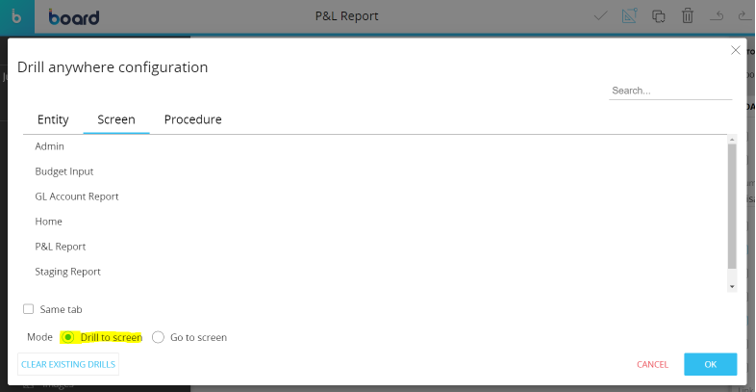
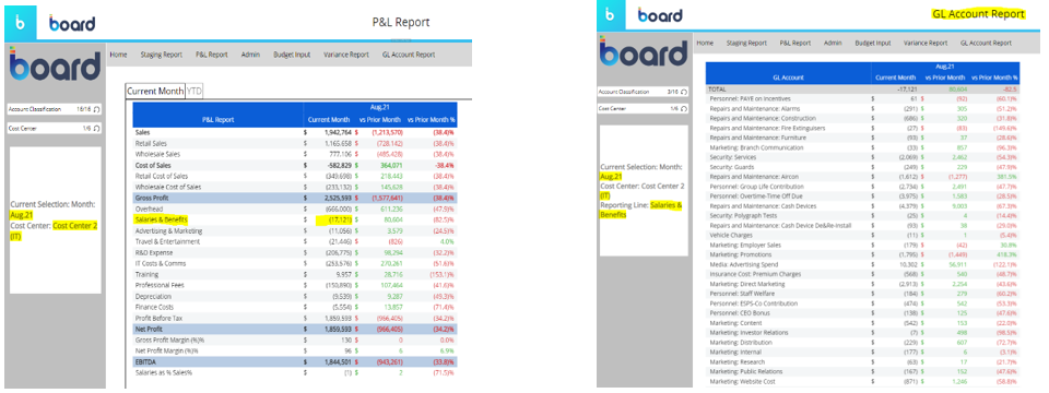
In the example below when the user double clicks on a row header ‘Salaries & Benefits’ line of the P&L Report, the selection is taken to GL Account Report carrying over even the original selections made in the P&L Report.
Therefore, on the GL Account Report, users would view data just for those GL Accounts that belong to the “Salaries & Benefits” P&L Report line item for the IT Cost Center for August 2021.
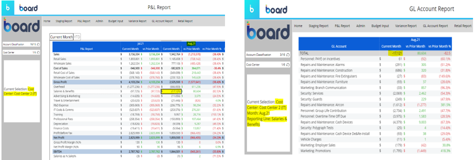
You can also configure a Drill-to screen from a cell case from the layout editor.
To do this, select the data view and open the layout editor, click on settings in the object preview panel to open the object properties panel and under the column appearance menu select the pencil icon to configure a Drill-to screen on one or more data blocks.
By doing as mentioned above, in analogy to the previous example, but instead of double-click on the row header ‘Salaries & Benefits‘, the user double clicks on a cell case, which is the combination of ‘Salaries & Benefits’ and ‘August 2021’, which produces the following result:
The ‘Drill-to screen’ mode can be combined with the ‘Dynamic Screen’ option, which dynamically redirects navigation to different screens.
This option allows to select of a block formula, an algorithm in the Data View, to dynamically change the Screen navigation based on another block value, a text cube containing screen names.
The ‘dynamic screen’ is available only for the cell case option and is configurable in the Data View properties below the column appearance menu.
This feature is useful to grant more flexibility to the user experience, for example by guiding navigation according to a binomial variable (0 or 1), e.g. whether the workflow status is open or closed.
2.2. Go To Screen
The ‘Go to screen’ mode opens the destination screen when the user double-clicks on a cell of a configured block or selects it and clicks on the drill-down icon.
The destination Screen will not inherit any selection from the Data View.
The ‘Go to Screen’ mode/option allows users to navigate from the current screen to the destination screen without carrying over the selections.
The ‘Go to Screen’ option is available in the Drill Anywhere configuration window where you choose the go-to screen mode.
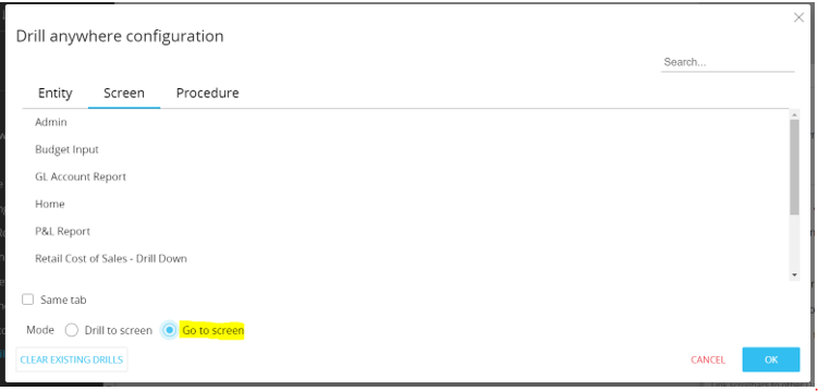
Also, the ‘Go to screen’ mode can be combined with the ‘Dynamic Screen’ option only for the cell case option and is configurable in the Data View properties below the column appearance menu.
Differently from the ‘Drill-to’ option, when a user navigates from one screen to the destination screen using the ‘Go to screen’ mode he/she can clear/reset the entity selection through pagers/selectors.
3. Conclusion
In conclusion, we can summarize the two options as follows:
Drill to Screen | Go to Screen |
|---|---|
This mode is useful if the requirement is to go to another screen with more detailed/granular data than the source screen. | This mode is useful if the requirement is to simply navigate between screens without overwriting screen selections on the destination screen. |
This mode can also be combined with the “Dynamic Screen” option where the screen navigation would be determined by the outcome of a column algorithm block. In this instance, the selection of the entities by row/column in the layout would be carried over to the destination screen. | This mode can also be combined with the “Dynamic Screen” option where the screen navigation would be determined by the outcome of a column algorithm block. However, in this instance, the selection of the entities by row/column in the layout would not be carried over to the destination screen. |
All Selections from the source screen are carried over to the destination screen thereby overwriting the selections on the destination screen. If this mode is configured on data view cells, then the selection of the combination of the entities by row and/or column will also be carried to the destination screen. | Selections are not carried over when the user navigates from the source to the destination screen. Can be combined with the “Apply Data Selection” property for selections to be carried over from the source screen to the destination screen. |
Restricts users from resetting entity selections through selectors and pagers. Users will need access to the screen selection window to reset entity selections or developers need to create procedures that can reset/remove the entity selections. | Allows users to reset entity selections through selectors and pagers. However, resetting entity selection is not possible if the “Go to Screen” navigation is combined with the “Apply Data Selection” property. |
Available in objects which have the Drill Anywhere Configuration property. | Available in objects that have the Drill Anywhere Configuration property as well as objects such as button, label, and capsule procedures. |
How to allocate with a dynamic driver

1. Abstract
In a complex application, we often face the need to perform allocations based on a different driver based on the situation, in most cases it is about cost allocation.
We will see in this article a step-by-step example of how to implement such a process.
2. Context
Cost allocation is an important process of any business, it plays a huge role in the decision-making, and that’s why we must design it in the best possible way.
Since there are many types of costs (fixed, variable, direct, indirect), the allocation driver can be different according to the perimeter.
Many points must be clearly defined during both the analysis and configuration phases, we will try to cover in this article two main pillars:
- Best practices in data modeling for allocation.
- Best practices in writing the allocation procedure.
3. Content
Let’s consider the following example:
For an international company with many legal entities all around the world, the need is to perform allocation for Group financial closing.
The starting point is the P&L cube, structured as follows:
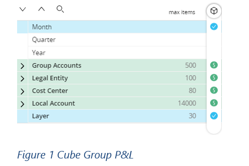
The need is to allocate costs based on the combination of one group account and one legal entity to another legal entity.
Note the presence of the “Layer” dimension, composed of these elements:
- Basis (the basis value that could be loaded, entered, or calculated)
- Local Adjustments
- Group Adjustments
- Group Elimination
- Allocation
The logic of this dimension is to maintain an audit trail of all data processes, where each element contains the delta from the base element, e.g.:
- To view loaded data → select layer = Basis
- To view loaded data after local adjustment → select layer = Basis + Local Adjustments
Following this logic, we will inject the allocated data into the “Allocation” layer of the same cube at the end of the allocation process.
3.1 Source Perimeter
The first step is to determine the source perimeter and identify the data to be allocated for which group account and legal entity (combination of sources).
In our example, the definition of the source scope is simply through a structured cube for Legal Entity and Group Account, and the user can define the scope through data entry.
The application must allow the user to choose the scope of origin according to the functional requirements, through a flexible interface like a dataview.
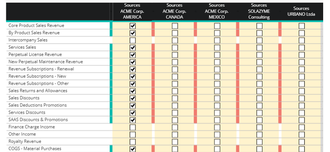
For ACME Corp. America, several group accounts were included in the source definition.
It is always preferable to use alerts to help the user with data entry and make sure to check all necessary combinations.
3.2 Target perimeter
As mentioned earlier, the need is to allocate data from one legal entity to another, so we need to define the mapping between the source legal entity and the target legal entity.
To define this mapping, it is necessary to have a cube structured by the Legal Entity (source) and the replicated entity of the Legal Entity (target).
The user performs data entry as follows:
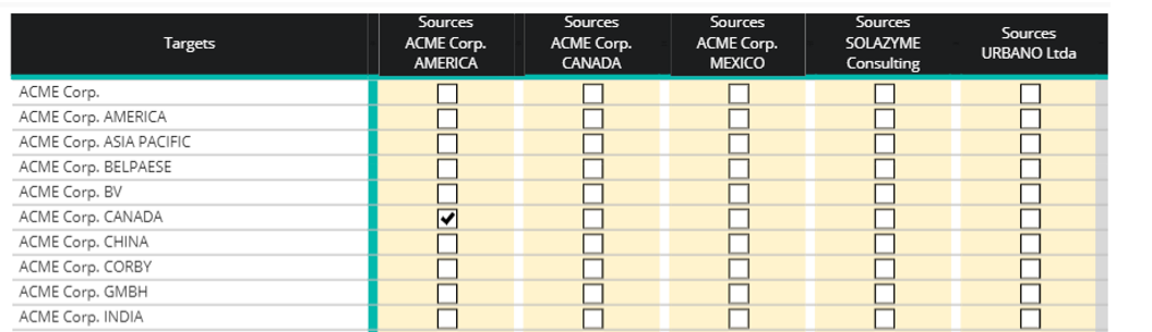
- source legal entity by columns
- target legal Entity by rows
ACME Corp. AMERICA has been entered as the source legal entity for ACME Corp. CANADA, which is the destination legal entity.
It is always preferable to use alerts to help the user check for each source whether it has a target or not.
3.3 Allocation driver
Now we need to define the allocation method for each source combination (Legal Entity and Group Account).
The available allocation methods are:
- Headcount
- Revenue
- Projects
- Assets
We need to create a dimension named “Allocation Keys” filled with the above elements and create a cube structured with the source dimensions (Legal Entity and Group Account) plus the Corp. Allocation Key dimension.
Note: the allocation driver can be loaded from a file or entered by users.
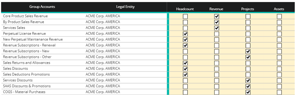
Note: the combination of visible sources is guided by section 3.1 Source perimeter.
3.4 Writing the procedure
Before allocation, it is necessary to collect the allocation driver data in a cube structured by {Month, Legal Entity, Allocation Keys}.
For example, the ‘Headcount’ data is retrieved from the HR module, while the ‘Revenue’ data is retrieved from the Sales module (Alternatively, this information can be uploaded to the Board application by users from an external layer).
Once the driver data has been successfully stored, we need to transfer it to the legal entity [R], which is the destination (target) legal entity.
Therefore, the allocation driver data cube structured by {Month, Legal Entity [R], Allocation Keys}.
Now we can perform the allocation by following these steps:
Step 1:
Select the correct source Layer (for example Layer = Basis, Local Adj, Group Adj)
Clean source data and keep only the combinations to allocate.
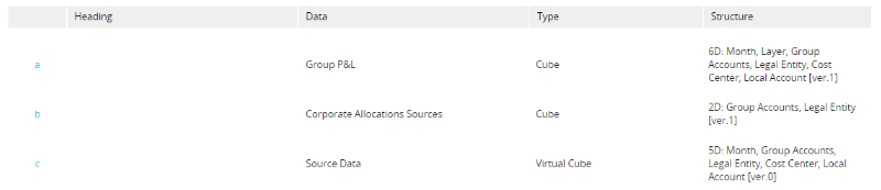
→ c = a*b
Step 2:
Populate the allocation methods with the driver values of each key method.
This is done in 2 dataflows:
- First add the Legal Entity [R] to the allocation methods
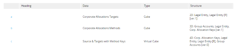
→ c = a*b
where block a is the result of the mapping of section 3.2 Target perimeter, and block b is the result of the mapping of section 3.3 Allocation driver.
2. Then populate the methods with the key values
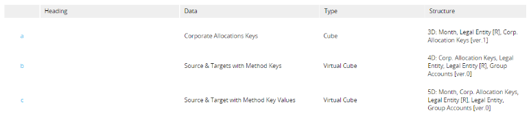
→ c = a*b
Step 3:
Adding the target dimension to the source data
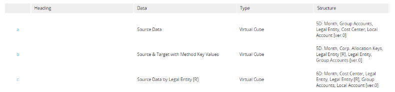
→ c = a*(b/b)
NB: in this dataflow, it is possible to replace the block b with the cube Corporate Allocations Targets, but it is more performant to use the temporary cube Source & Targets with Method Keys since its structure is more similar to the target cube.
Step 4:
Performing the allocation.
This is done in 2 dataflows:
- First we need to aggregate the allocation key values according to the source data structure in order to calculate the ratios.

→ b = a
2. Now that we have the allocation drivers at the detailed level (numerator) and also at the aggregate level (denominator), we can easily perform allocation as follows:
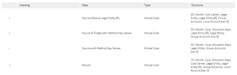
→ d = a*(b/c)
Step 5:
Now we have the “Results” cube that has the allocated data, note that the allocated data is on the Legal Entity [R] dimension, so we need to put it back by Legal Entity to be able to inject this result in the main cube “Actual P&L”.
This is done in 2 dataflows :
- The first one is just to get rid of the Legal Entity and allocate key dimensions

→ b = a
2. Secondly to move data from Legal Entity [R] to Legal Entity

→ b = a
Since we are working with the replicated entity Legal Entity [R], it is possible to simply copy cube a into cube b, Board will automatically do the mapping between the 2 entities, otherwise, if Legal Entity [R] is not a replicated entity, you must use a mapping cube to pass from cube ‘a’ to cube ‘b’ as follows :
- Create mapping cube structured by Legal Entity and Legal Entity [R].
- Create a temporary cube that has the same structure as cube “a” + Legal Entity
- Temp cube = cube * mapping
- Target cube (without the Legal Entity [R]) = temp cube
Step 6:
Now that the data has been allocated with the right structure (Legal Entity), the last step is simply to inject the data back into the main cube, but on a different layer:
Select Layer = Corporate Allocation
In that Layer we must cancel the initial value and add the new allocated value, so we do the following dataflow:
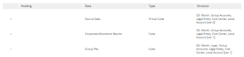
→ c = -a + b
3.5 Conclusion
This method does not work for multi-level allocation, but only for one level, which means that a legal entity can allocate costs to other legal Entities, but a target legal entity cannot reallocate to other legal entities.
The goal is to achieve this result by using the Layer Dimension.
Allocation results by accounts:
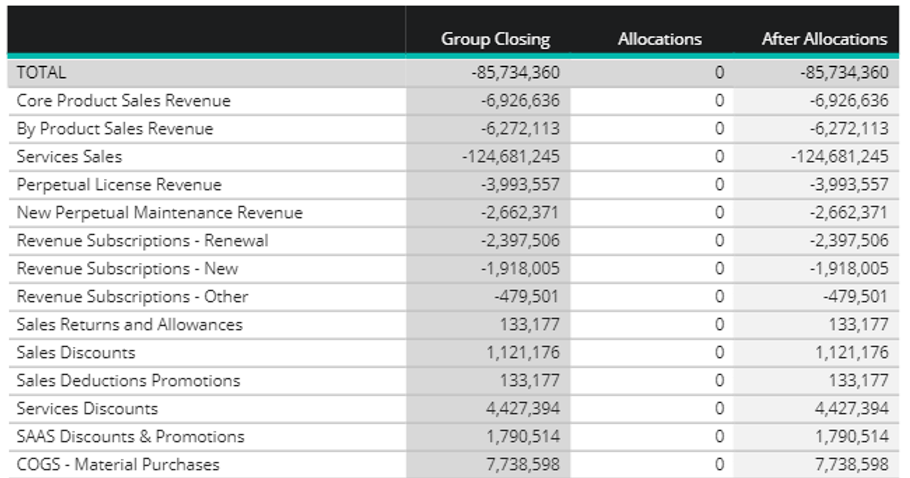
The sum of the allocated values for each account must be = 0 because the source and target accounts are the same.
Allocation results by Legal Entity:

The sum of allocated values for all legal entities must be = 0.
Related Content:
Capsule Procedure vs Datamodel Procedure

1. Abstract
While developers are facing procedure creation, they need to understand when it is appropriate to use data model procedures vs Capsule procedures.
2. Context
As developers, it is our responsibility to always keep the long-term maintainability of our solutions in mind. Procedures must be developed in a consistent and well-organized manner in order to allow other developers to step in and understand our work with minimal knowledge transfer time required. When creating a procedure, the 1st step is deciding whether we want a Capsule procedure or a Database procedure. This document provides specific guidance on when to use each type of procedure and how both can be used in concurrence to create a transparent and sustainable solution.
3. Content
3.1 When to use a Capsule procedure
Capsule procedures must be used for front-end actions or where user interaction is requiredsuch as screen interaction, saving data entry, refresh screen or navigation.
Examples:
- Go to Capsule
- Go to Screen
- Show Message
- Refresh Screen
- Interactive Selection
- Save Data Entry
- Undo Data Entry
- …
Other considerations on Capsule procedures are the following:
- Capsule procedures are saved within the Capsule (not the Data Model).
- Capsule procedures can only be invoked from Screens from within the same Capsule.
- Capsule procedures cannot be invoked by the scheduler.
- Capsule procedures can invoke procedures from multiple Data Models.
- Capsule procedures cannot be transported across environments individually. The whole Capsule needs to be transferred.
3.2 When to use a Data Model procedure
Data Model procedures must be used for back-end actions where there is no user interaction or front-end action required such as dataflows and all the calculations, simple or complex, data loads, data exports, Data Model maintenance and backup, BEAM, predictive and clustering models.
Other considerations on Data Model procedures are the following:
- Data Model procedures are saved within the Data Model (not the Capsule).
- Data Model procedures can be invoked from different Capsules.
- Data Model procedures can be invoked by the scheduler.
- Data Model procedures can be transported across environments individually (seeTransporter tool). This is a big pro for Data Model maintenance and solution life cycle management.
3.3 How to combine Capsule and Data Model procedures
The distinction between Capsule and Data Model procedures highlights how they can be effectively combined to ensure the most suitable sequence is invoked for the given process. In some cases, it is necessary to trigger calculations, KPIs, or allocation procedures when saving data using Capsule procedures. To achieve this, it is recommended to create a Capsule procedure specifically for saving data and then call a Data Model procedure that handles data flows and performs calculations. This approach ensures the process is optimized and efficient.
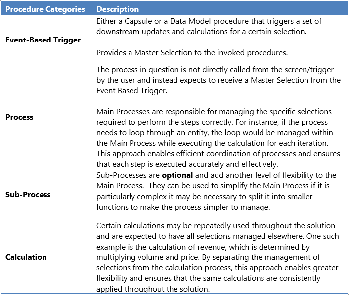
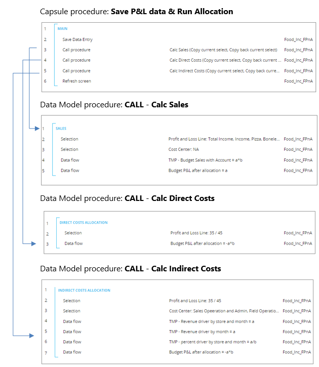
Example: Capsule Procedure that calls Data Model Procedures
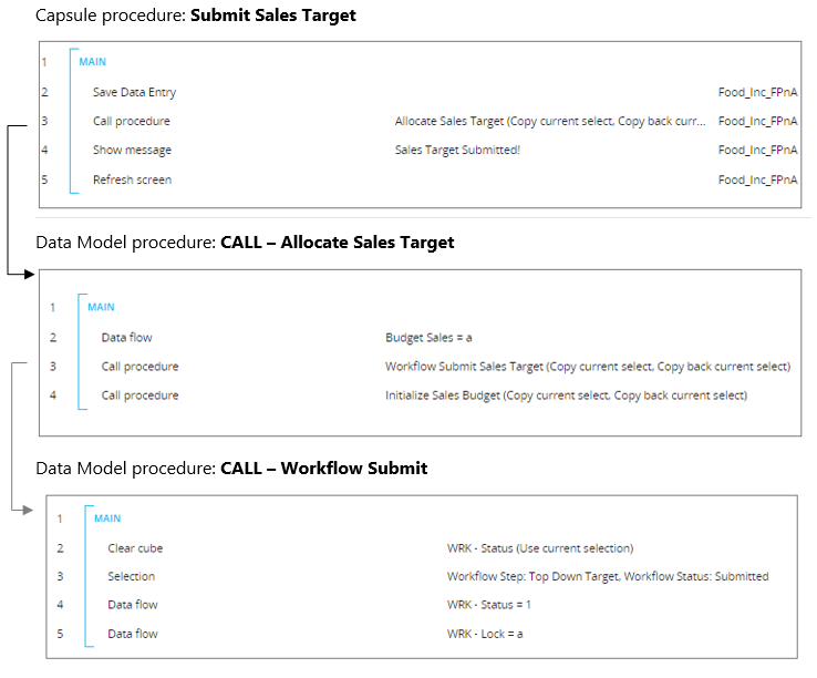
Example: Capsule Procedure that calls nested Data Model Procedures
Remarks:
- Copy Current Select & Copy Back Current Select: the main procedure selection must be driven by the screen selection, the security, managed in the “Event-based trigger” or a mix of all of the previous. In the called or nested procedures, it may be necessary to have ad hoc selection to drive the specific calculation or sub-processes. When a procedure is called is good practice to flag the Copy Current Select option but never Copy back Current Select when the called procedure ends and we are back to the main process or to the event-based trigger. This is to avoid that the ad hoc selections, that are made for the specific subprocesses, are also affecting the active selection in all the other called procedures called.
- Make sure that the Run on Current DB option is always flagged.
- Identify procedures that are called from other procedures with the prefix CALL. This is important to evaluate any possible impact in case of any modifications in the called procedure.
- Do not exceed nesting procedures. No more than three nested levels. This is to keep the process flow clear and the maintenance streamlined.
Custom Time Entities – Generic Month example

1. Abstract
Custom time entities are a subset within the time range section in the BOARD database.
They are mainly adopted during the application to intercept those time analyses which cannot be implemented with only the standard time function available by default in the BOARD data model.
Since they are limited in BOARD, they must be carefully managed.
Moreover, regardless of the just-mentioned limitation, it is important to keep them updated and integrated to always get a consistent time tree, which is one of the main dimensions of each BOARD data model.
The purpose of this document would be to give best practices on the custom time entities definition and to explain how to use them.
2. Context
Sometimes the company may need to handle customized time dimensions to generate very specific time analyses.
During the requirement gathering, one of the first decisions is whether to implement the business request with the creation of a custom time entity or with an entity outside the time range.
Custom time entities are limited, with 4 slots available in BOARD and therefore during the analysis phase, the developer must open a discussion before taking a decision based on the pros and cons of having it.
This is a crucial decision, as it will affect the entire data model and make the maintenance of the application based on it a bit more complex.
3. Content
With custom time entities you can define ad-hoc time entities.
For instance, you might encounter a company’s request where the company may need to handle very specific analyses by generic month (Jan, Feb, March, etc), 4-4-5 weeks, Season or Promotion, and so on.
After discussion with the customer on the needs and output to be achieved in Board, a technical challenge comes up.
The custom time entity must be set up and integrated with the existing time tree, which implies the definition and the maintenance over the time of the relationship between the custom time entity and the existing time schema.
3.1 Definition and population
Let us see how to create and inject the ‘generic’ month as a custom time entity into Board.
Open the time range tile.
Click custom entities, pick up the first custom time entity named as ‘_Time1’ and then provide a valid name.
Add manually the new members. Here the developer has two options:
- insert the members manually;
- copy and paste members from an existing file.
At this stage, you need to do a couple of things:
1. Click custom relationships and set up the relationship by placing the generic month on top of the month.
By doing this you are creating a new branch for the generic month, but month members still are not linked to it.
Click Save changes.
Note that all direct and indirect relationships must be always defined, no orphan (stand-alone) entities are allowed.
In the rather unlikely but possible scenario, if at some point in the project it is necessary to discharge the ‘generic’ month, it is not enough to remove the relationship, one must also empty the entity.
In general, the above statement must be applied against any given custom time entity.
A direct relationship is a one-level child → parent relationship.
In our example, Month → Generic Month is a direct relationship.
An indirect relationship is a child → grand-parent relationship, for instance, if the Day entity is enabled for this database, then Month is a parent of the Day, therefore you must define also the indirect relationship Day → Generic Month.
2. Once complete we can go within the Data reader section to feed the relationship up in Board.
Click new data reader to get access the Data reader configuration and select the data source Text File.
The file to be read looks like the following:
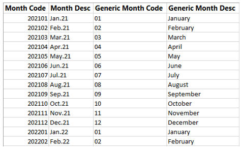
3. Within the data reader, map the month and generic month entities with their counterpart taken from the file.
Click save changes and run the data reader protocol.
At this stage, the entity is populated and the relationships are defined, therefore the entity can be used.
NOTE: if we want to use this entity in combination with the standard time functions available in Board (i.e. Prev. Year, offset, etc .) we would need to define also the “mask” setting. Please refer to the Board Manual to see how this can be done.
4. Point of attention
Since the ‘generic’ month is injected into the time tree of the data model, please note that from this moment onward any increase applied to the time range (i.e., increase of the ‘To Year’ value) implies even updating the relationship for the new month members in scope.
In practice, you must:
- Open the file to be read in BOARD and update accordingly with the time range definition, this means adding the new combinations between month and generic month.
- Get back to the second step of the process and follow the remaining steps.
Re: Broadcasting & Notification Tool
Thanks @Abdelhadi Babaali for the insights on this subject!